
Wednesday, 14 January, 2026г.


Где искать: по сайтам Запорожской области, статьи, видео ролики
пример: покупка автомобиля в Запорожье
Square wave & triangle wave oscillator with 555 chip + FET (40 Hz-18 KHz) schematic
 У вашего броузера проблема в совместимости с HTML5
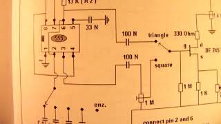
Schematic from a simple but very properly working square wave-triangle wave oscillator between 40 Hertz and 18 KHz that can be made with a cheap 555 timer chip. Don't forget to solder a wire between pin 2 and 6!
All connections and how to make it are in the video. Very easy to make and very useful for testing audio amplifiers, driving power stages, etc.
Because of the fact that the triangle wave has less energy-out compared to the square wave, its input to the FET BF 245 B has to adapted somewhat (1 M potmeter) so that, at the source from that FET, we can take both signals (square wave and triangle wave) out on the same output level.
The FET is not critical, you can use the BF 245 A or BF 245 B or BF 245 C or the J 310 FET. These are all N-FETS, search their pin connections on the internet/www to find out what is “gate” “drain” and “source”.
Though the BF 245 A is quite vulnerable for static charges on the gate (types B and C less) and easily gets defective. But anyway, in this circuit there is no risk of too high static charges on the gate from the FET.
The circuit, of course, needs a stabilized voltage (all measuring oscillators need that) and that is realized with a 7812. But of course a series-transistor with a 13 Volt zener in the base-ground line can do the same job, many series-transisor-regulated-voltage sources are published on my YT Channel, go e.g. to the video “Radiofun232 on You Tube” for more information.
Whatever: the circuit with the 7812 stabilzer is the cheapest and the best and easiest voltage stabilizing circuit.
Important: the minimum power supply capacitor that the 7812 needs at its input is 4700 uF. Bridge that capacitor with a resistor from 470 K up to 1 M and a non-polar capacitor from 0,1 uF (100 N). Then you have no risks about ripple problems, HF disturbing signals entering the 555 chip, etc.
All the videos hat I have published on You Tube can be found via my Channel Trailer: Link is
https://youtu.be/xbgQ8T3oqh4
In thematic order you can find these video’s under the “comments” section. My books about electronics are available via the website from “Lulu”, search for author “Ko Tilman” there.
Link is https://www.lulu.com/shop/search.ep?keyWords=ko+tilman&type=
My books are also available via Barnes and Noble and via Amazon.
Regarding all my video’s: I constantly keep them actual, so the original video’s with the most recent information are always on YouTube. That is the source, and search there. When my video’s are reproduced or re-edited on other websites/channels you can not (!) be sure about the original content (=really working electronics) and important adaptations to the circuits.
Be aware of that, I saw on the internet many of my circuits reproduced in a poor or even not proper way. I can not help that, sorry.
Теги:
radiofun232 radioam232 ko tilman tilman triangle wave oscillator oscillator triangle wave square wave square wacve generator schematics 1 book books lulu lulu website
Похожие видео


Мой аккаунт