
Wednesday, 14 January, 2026г.


Где искать: по сайтам Запорожской области, статьи, видео ролики
пример: покупка автомобиля в Запорожье
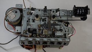
Sanyo 9980LU Boombox AM/SW/LW Alignment -- PART 1
 У вашего броузера проблема в совместимости с HTML5
Correction: In the last adjustment I say "AM oscillator high-end" Correct is "AM antenna high-end adjustment."
Video is somewhat long, convoluted, and most likely superfluous ; it is therefore in two parts. A few scenes had to be filmed again because I accidentally deleted the originals. There was an overall improvement after alignment.
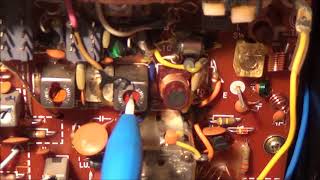
In this part the setup is shown and then the IF (intermediate frequency), AM oscillator, and AM antenna (RF) alignment is done.
A non-metallic screwdriver must be used and the the coil of the rod antenna must be fixed into position by a drop of wax once the final position is found. The output from the signal generator must be kept as low as possible but still provide a reliable signal. The oscillator setting can be checked by tuning into a station with a known frequency and checking the dial indicator position. While making the adjustments the tuning dial was always set to a position where there were no known stations. I elected to use the external speaker output to hook up the AC voltmeter to, but could have hooked the voltmeter across a speaker voice coil if I had wanted too.
The alignment did have a definite order: (1) the IF circuit; (2) the oscillator circuit; and then the antenna (RF) circuit. Meaning, working backwards toward the antenna. All adjustments were done twice.
The service manual recommended that a 400Hz signal be used as a modulating tone at 30% modulation.
Похожие видео
Мой аккаунт