
Monday, 12 January, 2026г.


Где искать: по сайтам Запорожской области, статьи, видео ролики
пример: покупка автомобиля в Запорожье
Cypress Academy: PSoC 101- Lesson 7: Timer, Counter and PWM Component
 У вашего броузера проблема в совместимости с HTML5
http://www.futureelectronics.com/en/Search.aspx?dsNav=Ntk:PartNumberSearch%7cPSoC+101%7c1%7c,Ny:True,Nea:True
1. Make a copy of the Basic Counter project
2. Delete the counter and the logic gates
3. Edit each pin to be for SW only, initially high
4. Add a TCPWM Timer Counter, name it Counter, enable the count terminal for falling edge, and interrupt on terminal count and period of 2
5. Add a clock
6. Connect SW2 to the count terminal
7. In C, start the Timer
8. Write an ISR handler that toggles Pin_GREEN – explain the Clear Interrupt argument
9. Build and program
10. Press three times to toggle the pin
11. Action: control the red LED in the same way as the red one but in hardware – use a TFF on the overflow terminal to drive the LED pin directly
http://www.futureelectronics.com/en/Search.aspx?dsNav=Ntk:ManufacturerPartNumberUpshiftedSearch%7c*CY8CKIT%2f-042*%7c1%7c,Ny:True,Nea:True
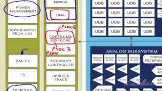
My name is Alan Hawse and this is PSoC 101. Now I am going to introduce you to a more powerful counter. This counter is implemented in one of the special Timer/Counter/PWM blocks or TCPWM in the PSoC device. The next three lessons show you how to use three of TCPWM options.
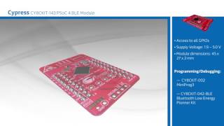
http://www.futureelectronics.com/en/technologies/development-tools/rf-wireless/Pages/1050692-CY8CKIT-042-BLE.aspx?IM=0
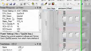
Make a copy of the BasicCounter project then delete the BasicCounter and the logic gates. Find a TCPWM-based Counter in the component catalog and then drop it into the schematic. This component needs to have an input clock signal; so grab a clock and attach it to the clock input like this. The default 12MHz frequency is fine for what we need. In the Counter customizer you can see that it can be also be a Timer, Quadrature Decoder or PWM. You should leave it as a Counter and change the name, then enable counting on a falling edge, with an interrupt on terminal count and a period of two. The idea of this project is that it will count button presses and when the counter reaches zero the interrupt will fire. In order for this to happen you need to attach an Interrupt component to the interrupt terminal of the counter.
That’s quite a lot of editing in the component. To understand these choices a little deeper, go to the component datasheet, which explains the options clearly and lists the API functions that will be generated.
Before writing the C code you should generate the API files. You can do that by just building the project or, to finish a little quicker, press the Generate Application button. This does a partial build of the project – leaving out the compile and link stages. With the APIs generated, you get the benefit of predictive typing in PSoC Creator.
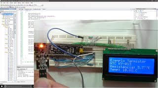
First, you need to turn on the Counter component. Unlike the simple hardware-only components (flip-flops and BasicCounter) the TCPWM-based counter needs to be initialized in firmware. To do that call the component Start function. You must also register the interrupt handler using the StartEx function. Don’t forget the macro to enable global interrupts. Then move above the main function and write the actual interrupt handler. Use the CY_ISR macro again and write code to toggle the green LED pin. To clear the interrupt use the ClearInterrupt function, which requires an argument to identify which interrupt source to clear. You are using the terminal count as the source of the interrupt, so the macro to clear that source is the name of your component with I N T R underscore MASK underscore T C.
Now, when you program the kit with this project, you need to press the switch three times to make the LED toggle. That is because the counter is counting down from a period of two. It decrements on every falling edge from the switch, because it is active low, and asserts a terminal count interrupt when the counter reaches zero. It also reloads the counter back to the initial period value so the Counter immediately restarts counting down from 2.
When you make this project you should extend it by toggling the red LED from hardware, instead of the ISR. To do this use a toggle flip-flop connected to the overflow terminal, labeled “ov”, which generates a single-cycle clock pulse when TC is asserted.
As always you are welcome to email me at [email protected].
Теги:
Cypress Semiconductor Cypress Academy Toggle Flip-Flop Basic Counter Timer TCPWM Quadrature Decoder PWM Interrupt PSoC PSoC 101 PSoC Creator PSoC Creator 3.3 ARM CPU serial communication system UART I2C SPI timers counters PWMs CapSense Pioneer kit CY8CKIT-042 CY8CKIT-044 CY8CKIT-046 CY8CKIT-042-ble IOs pins Hardware Pins
Похожие видео
Мой аккаунт