
Friday, 19 December, 2025г.


Где искать: по сайтам Запорожской области, статьи, видео ролики
пример: покупка автомобиля в Запорожье
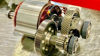
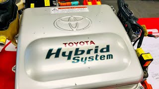
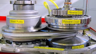
Chevrolet Bolt EV Traction Motor - Deep Dive
 У вашего броузера проблема в совместимости с HTML5
Join us for a deep dive into the incredible Chevrolet Bolt EV Traction Motor (part of the 1ET25 Drive Unit). Watch the drive unit disassembly and learn about the internal parts.
Video Timeline:
Video introduction at 0:12
Drive Unit (DU) Specifications at 0:36
MUST SEE - Motor torque verses torque to the wheels at 0:55
Lubrication and coolant at 3:57
Drive Unit Identification and Option Codes at 4:27
See the Transmission Range Selector Actuator and shifter at 5:34
Transmission fluid fill, drain, and fluid level checking at 6:48
Transmission electric fluid pump (12V) operation at 8:52
Motor resolver and fluid temperature sensor connector at 9:53
Rear view and components at 10:52
Transmission holding fixture at 11:55
Transmission weight at 12:31
Electric Gerotor type fluid pump removal at 12:40
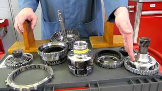
Removal of the Output Shafts at 13:39
Transmission Range Selector Actuator removal at 16:53
Transmission Case (Right Side Cover) removal at 18:03
Shift linkage, park pawl, and Internal Mode Switch (IMS) at 18:56
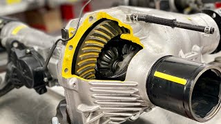
Ring gear, differential, bearings, and end-play shims at 19:42
Non-reusable aluminum gaskets at 22:32
Oil baffle and magnet at 22:41
Differential case removal at 23:43
Transmission Case Cover (Left Side Cover) removal at 24:44
Oil filter, Resolver, and fluid temperature sensor at 26:46
End view of motor rotor, stator, and lubrication/cooling channel at 27:18
Fluid filter removal and positioning at 28:10
Resolver removal at 28:48
Bearing center support removal at 30:05
Counter drive gear removal at 30:35
Lubrication channel and three-phase cable nut retainer removal at 31:09
Oil distribution channel removal at 31:32
Preparation for rotor removal at 31:45
MUST SEE - Rotor centering tool installation at 32:58
Oil sump cover removal at 37:14
Coolant sump cover removal at 38:02
Installation of Rotor puller tools at 39:16
MUST SEE - Pulling the Rotor from the Stator at 43:38
Rotor components at 49:04
Stator removal procedure at 50:42
MUST SEE - Stator unique design review at 51:50
The "Small Block Chevrolet" of electric motors at 52:01
THREE MOVING PARTS and reliability at 54:56
Video wrap-up at 57:33
Bearing Grey Coating Information Update:
Thank you to SeanBZA! "Grey coating is an insulator, to prevent circulating currents through the bearings from any slight imbalance in magnetic field in the motor. there is a single bearing that is grounded ( the shiny one) to prevent charge build up on the rotor and a flash over to the frame, but the rest have to be insulated so they do not have a shorted turn through the frame that can cause a high circulating current through the bearings that rapidly erodes them through arcing. There are current paths for this current via things like the output shafts and the selector forks, but they probably assumed that, being long thin wall section steel assemblies, this long path would both keep the current low enough not to cause any major extra wear, and also the long output shaft would be mostly self cancelling field wise as well.
A lot of larger electric motors handle this with one end having coated bearings, or they make them with ceramic bearing balls inside, or just make both sides with insulated bearing mounting frames, and provide a grounding carbon brush assembly to handle shaft grounding. Drawback of the coated bearing is that you have to ensure that there is absolutely no damage to the coating on the outside and the side facing the frame, so that there is no metal to metal path. However, depending on the exact coating applied, this coat can be both insulating and tougher than the steel of the bearing itself. grey would point to a spray on ceramic coating, probably vacuum deposited before final bearing assembly or applied as a plasma coating."
Shift Lever and Actuator system update:
The shift lever sends a request to a chassis control module (CCM) for the trans range desired. The CCM commands the shift actuator to move the mechanical linkage to the desired position. The internal mode switch (position sensor) inside the trans sends a signal verifying the current gear range selected. The systems also has a "default to park" option when a malfunction occurs which will prevent vehicle movement until the fault is repaired.
2017-2019 Chevrolet Bolt EV Drive Unit disassembly - A Youtube first!
Weber State University (WSU) - Department of Automotive Technology - Ardell Brown Technology Wing - Transmission Lab.
This is the seventh in a series of videos on the 2017-2019 Chevrolet Bolt EV
W.S.U is a leader in Hybrid and Electric Vehicle education. We offer both online training and hands-on training classes on Hybrid and Electric Vehicles to the general public. Visit www.weber.edu/evtraining for more information.
This video was created and edited by Professor John D. Kelly at WSU. For a full biography, see http://www.weber.edu/automotive/J_Kelly.html
Donate to the Department of Automotive Technology at Weber State University here: http://advancement.weber.edu/givetowsu
Теги:
ASE NATEF Guy in wheelchair Weber State University Professor #boltev Traction Motor Weber State Automotive NACAT Drive Unit 1ET25 John D. Kelly WSU Chevrolet Bolt EV CAT STEM
Похожие видео
Мой аккаунт